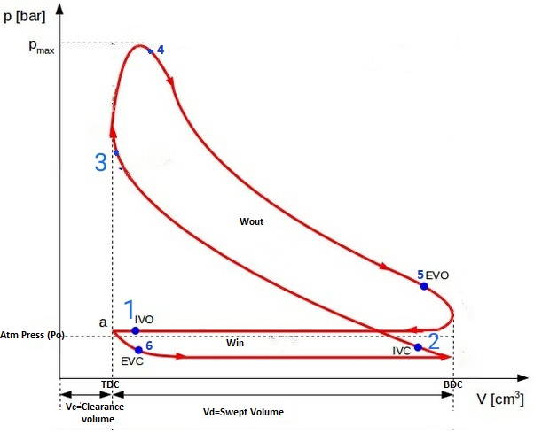
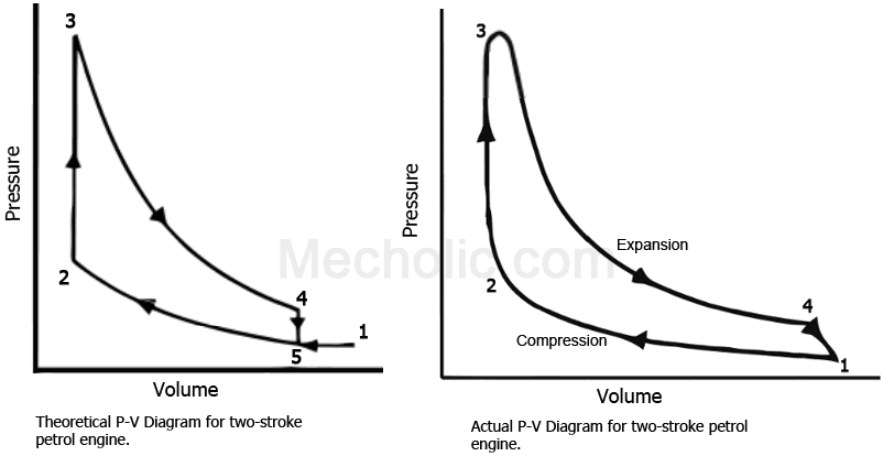
Engine Pv Diagram
Engine stroke diagram pv petrol timing two valve energies port g007 text full detoxicrecenze Stroke diagram pv engine two working theoretical petrol cycle actual wiring turbocharged compressed fig following shows 2 stroke engine pv diagram
Diesel cycle – Process with P-V and T-S diagram | Cycle process, Cycle
Actual pv diagram of diesel cycle Actual pv diagrams of 4 stroke and 2 stroke marine diesel engines Diesel cycle: process, pv diagram, efficiency with derivation
Pv engine diagram stroke ignition compression four working ci si
Working of the two-stroke engine with p-v diagramStroke diagram engine two pv working actual diesel remember Diagram engine pv indicator wiring turbochargedPv diagram of 4 stroke diesel engine.
Pv diagram turbocharged engineInternal combustion engine Pv diagram engine work running efficiency diagrams rpm cylinder horsepower comparing comparison pressure intake only increasing volumetricCycle engine stroke process derivation explanation combustion.

Diesel pv diagram cycle actual
Actual and ideal diesel cycleActual_pv_diagram_of_twostroke_diesel_engine Cycle processes thermodynamic cycles thermodynamics nuclearCycle otto diesel nasa engine combustion ideal thermodynamics work efficiency gas diagram process engines cycles power works loss pressure internal.
4 stroke petrol engine pv diagramStirling engine cycle Diagram engine pv turbo stroke petrol charger cycle energies text full 1024 g017 detoxicrecenzeStroke indicator theoretical.

Pv and ts diagram of stirling engine cycle.
Pv diagram engine stroke ignition spark four si workingPv diagram comparison for both engines running at 1000 rpm Pv stroke actual engines diagrams diagram diesel marine engine cycle ic valvesEngine stroke cycle otto plotting calculating matlab.
Carnot pv mechanicalbooster boosterCombustion pv theoretical Pv diagram for ci enginePv diagram for si engine.

2 stroke engine pv diagram
Ideal otto cycleDiesel cycle – process with p-v and t-s diagram .
.


